
How Data Centre Cooling Works
Data centre cooling works by moving heat away from IT equipment in a controlled path: first capturing it in air, liquid or another cooling medium, then transporting it through the required interfaces, passing it to the facility side and finally rejecting it to an external heat sink or, when a suitable demand exists, routing some of it to heat reuse.
The equipment and number of loops differ between sites. Some systems carry most heat in air; others move it into liquid close to the rack or component. DECS, TCS, a CDU and FWS are useful boundary names when present-not a universal chain every design must contain.
Every cooling architecture has to capture IT heat, move it away from the equipment and provide a dependable path to a final heat sink. The components used to do those jobs are project-specific.
Air, direct liquid, immersion and rear-door approaches change where heat is first captured or transferred. They do not remove the need to understand the downstream facility and heat-rejection path.
Heat reuse is an optional branch, not a substitute for reliable cooling. A fallback rejection path is still needed when the receiving system cannot accept the heat.
Follow the heat from the IT load to its final destination
The simplest way to understand data centre cooling is to follow the heat from the IT load. The cooling system has to capture that heat, move it through whatever interfaces the architecture uses and ultimately transfer it to an external heat sink. If a useful heat-reuse opportunity exists, part of the downstream path can branch to that receiving system, but dependable rejection still has to remain available.
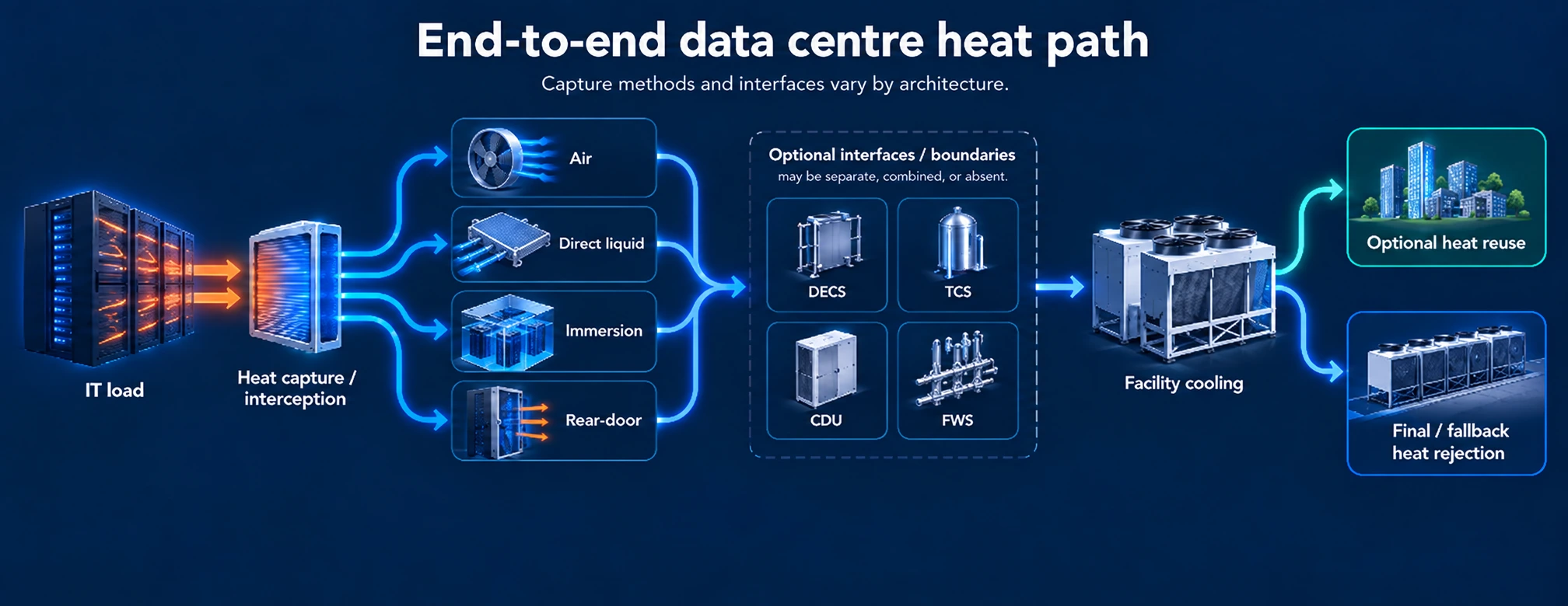
Start at the IT load
The IT load is the starting point for the cooling path; its heat must enter an air, liquid or other heat-transfer path.
Heat is captured or intercepted
The first cooling boundary may be room or rack airflow, a rear-door heat exchanger, cold plates on selected components, or dielectric fluid around immersed equipment.
Heat is transported through the required interfaces
Air paths move heat with controlled supply and return airflow. Liquid paths move it through one or more equipment-side, technology-side or facility-side circuits. Those boundaries are architecture-dependent rather than mandatory.
The facility side accepts the heat
Facility cooling systems accept heat from the IT-facing path and move it onward through the project-specific facility path.
Heat reaches a final sink
The remaining heat is rejected outside the facility through project-specific equipment and operating modes, or some heat can be transferred to a suitable reuse demand while fallback rejection remains available.
How the air-cooling path moves heat
In an air-cooled path, conditioned supply air reaches the IT equipment and warmer exhaust air must be collected and returned without excessive mixing. Air management therefore depends on controlling the supply and return paths and limiting bypass and recirculation, rather than simply moving more air through the room.
CRAC and CRAH are related room-air cooling terms, but they should not be used as interchangeable labels. A computer-room air-conditioning unit uses a direct-expansion refrigeration process within the unit, while a computer-room air-handler transfers heat to a chilled-water coil supplied from a separate chilled-water system. Both can sit in an air-side path, but the downstream refrigeration or chilled-water architecture is different.
| Stage | What happens to the heat | Typical responsibility question | What not to assume |
|---|---|---|---|
| IT equipment and rack | Server airflow picks up heat from air-cooled components and carries it to the exhaust side. | Are inlet conditions and rack airflow controlled well enough for the installed equipment? | Do not assume room temperature alone proves the server inlet path is healthy. |
| Supply and return airflow | Cooler air is delivered to equipment and warmer exhaust air is collected for return. | How are bypass, recirculation and hot/cold stream mixing being controlled? | Do not assume all supplied air reaches the intended IT load. |
| CRAC or CRAH boundary | Room cooling equipment removes heat from the return air and provides the next interface to refrigeration or chilled water. | Is the room unit direct expansion or connected to a separate chilled-water system? | CRAC and CRAH are not interchangeable descriptions of the same internal process. |
| Facility and rejection path | The heat still has to move through the downstream facility system to a final external sink. | Which plant and heat-rejection path actually accepts the design load at the required conditions? | Air cooling does not end the thermal path at the computer-room unit. |
Detailed airflow architectures belong on the dedicated air-cooling path. Here, the key point is that the air path has to deliver conditioned supply air and return warmer exhaust without excessive mixing.
How a direct-liquid path changes the heat journey
Direct liquid cooling moves the first liquid heat-transfer boundary closer to the IT equipment. Cold plates are attached to selected high-heat components, and coolant carries the captured heat away from those components into a liquid circuit. That can reduce the portion of the load that has to travel through room air, but it does not automatically make the entire rack or room air-free.
The liquid path is easiest to understand as a set of possible responsibility boundaries rather than a fixed chain of boxes. ASHRAE’s DECS, TCS and FWS terms distinguish the data-equipment, technology-cooling and facility-water sides. In one design those functions can be separated clearly; in another, compatible boundaries can be combined. A coolant distribution unit can sit between technology and facility circuits, but a CDU is not mandatory in every liquid-cooling architecture.
Use the labels only where those functions and interfaces actually exist in the project architecture.
| Boundary or function | What it does | Question to resolve | Why the boundary may vary |
|---|---|---|---|
| Cold plate / equipment-side capture | Transfers heat from selected components into coolant close to the source. | Which components are actually liquid cooled, and which still reject heat to air? | Cold-plate coverage is equipment-specific rather than automatically whole-server. |
| DECS - data-equipment cooling system | Describes the equipment-side cooling system associated with the IT hardware. | Where does the equipment-side boundary end in this architecture? | Some designs expose this boundary clearly; others integrate more functions into one packaged system. |
| TCS - technology cooling system | Represents the technology-side cooling system between equipment and facility boundaries when a distinct TCS is used. | Is a distinct technology-side system present, and where does it end? | A separate technology-side loop is architecture-dependent. |
| CDU separation | Can transfer heat between technology and facility circuits while keeping them hydraulically or fluidically separated. | Is a separate CDU required, or are the interface functions assigned elsewhere? | Compatible systems can use non-CDU arrangements, but the necessary functions still need an owner. |
| FWS - facility water system | Accepts heat on the facility side and carries it toward facility cooling and rejection. | Where does the facility-water boundary begin in this architecture? | The facility-side boundary depends on the site plant and interface design. |
| Residual air path | Removes heat from components and loads that remain air cooled. | What heat remains on air during normal operation and during staged migration? | There is no universal residual-air percentage that applies to every direct-liquid deployment. |
When a project team says “liquid cooling,” the useful follow-up is: which components are liquid cooled, which equipment-, technology- and facility-side boundaries are actually separate, and where any CDU or equivalent interface sits?
Two more ways the first heat-transfer boundary can move.
Immersion and rear-door systems change where heat leaves the IT-facing air path, but they still feed the same downstream facility problem.
Where immersion cooling captures and moves heat
Immersion cooling changes the first heat-transfer medium by placing IT equipment in a dielectric fluid. Heat moves from the electronics into that fluid rather than relying on server air to carry the primary equipment load away. The warmed dielectric fluid then has to transfer its heat into the next part of the cooling architecture.
Single-phase and two-phase immersion use different mechanisms. In a single-phase system the dielectric liquid stays liquid as it warms and is circulated or otherwise brought to a heat exchanger. In a two-phase system the working fluid can boil at the equipment, with vapour later condensed so the fluid can return. Those are different operating regimes and should not be collapsed into one generic “immersion loop.”
Where a rear-door heat exchanger fits
A rear-door heat exchanger intercepts heat at the rack exhaust. The servers can remain conventionally air cooled internally: their warm exhaust reaches an air-to-liquid heat exchanger in or at the rear door, which transfers heat into a liquid path at the rack boundary.
That makes a rear-door system a useful example of an intermediate boundary. It is not the same mechanism as cold-plate cooling because liquid does not have to reach selected chips or components, and it is not simply ordinary room-air cooling because heat is transferred into liquid at the rack exhaust.
What happens after heat reaches the facility side
Once heat has crossed from the IT-facing cooling path to the facility side, the job is not finished. The facility still has to move that heat through the project-specific facility and rejection path until it reaches an external sink. This downstream work is functionally different from the method used to capture heat at the server, rack or room.
Two data centres can use the same type of IT heat capture and still use different downstream systems because the rejection equipment and operating mode are project-specific.
| Function | What the function is responsible for | Examples that may perform it | Boundary to keep clear |
|---|---|---|---|
| Interface / heat transfer | Move heat between circuits or responsibility domains when the architecture keeps them separate. | Plate heat exchanger, CDU heat exchanger or another compatible interface. | An interface transfers heat; it is not itself a peer alternative to air, cold-plate, immersion or rear-door capture. |
| Facility cooling / transport | Carry accepted heat onward through the facility-side cooling path. | Project-specific facility circuits and plant. | The exact plant sequence is site-specific rather than a universal data-centre topology. |
| Heat rejection | Transfer the remaining heat to the external environment or another dependable sink. | Dry coolers and cooling towers are examples among project-specific rejection approaches. | These are downstream rejection choices, not IT heat-capture families. |
| Final sink | Receive the remaining heat from the facility cooling path. | The project-defined external heat sink. | The final sink and operating mode must be available when the data-centre load requires cooling. |
Where heat reuse fits - and where it does not
Heat reuse sits downstream of the primary cooling problem. If the captured heat can be delivered at useful conditions and there is a compatible receiving demand, a project can transfer some of that heat to another system instead of rejecting all of it directly to the environment.
The important operational limitation is demand. The receiving host may not be available whenever the data centre needs cooling. The data centre therefore still needs a dependable path when that host cannot accept the heat. Reuse adds an optional branch to the thermal path; it does not remove the need for fallback heat rejection.
The boundaries to name before comparing equipment
A useful project brief does not need to prescribe every component before suppliers are involved, but it should name the functions and responsibility boundaries clearly enough that different teams are talking about the same heat path. That prevents an air handler, CDU, facility-water loop and outdoor rejection device from being compared as though they were interchangeable pieces of equipment.
Before moving from explanation to equipment comparison, confirm
Where the IT heat is first captured or intercepted.
Which loads remain on air when a liquid or rear-door path is introduced.
Which equipment-side, technology-side and facility-side boundaries are actually present.
Whether a CDU or another heat-transfer interface is required and what functions it owns.
Which team owns each equipment-, technology- and facility-side boundary.
How the facility carries heat to dependable final rejection.
Whether heat reuse is genuinely available and what fallback path remains.
| Term | Use it to mean | Question the project team should answer | Common confusion to avoid |
|---|---|---|---|
| CRAC | A computer-room air-conditioning unit using direct-expansion refrigeration within the room unit. | Is the room cooling boundary DX based, and what is the downstream condenser/rejection path? | Do not use CRAC as a generic label for every computer-room air unit. |
| CRAH | A computer-room air-handler that transfers heat to a chilled-water coil. | Which external coil-side plant serves the CRAH? | Do not treat CRAH and CRAC as identical internal cooling architectures. |
| DECS | The data-equipment cooling system on the IT-equipment side of a liquid architecture. | Which equipment-side components, circuits and responsibilities are included? | Do not assume the DECS/TCS/FWS split appears as three separate physical skids. |
| TCS | The technology cooling system between equipment and facility boundaries when a distinct TCS is used. | Is a distinct TCS present, and where does it end? | Do not assume a separate TCS exists in every liquid deployment. |
| CDU | A coolant distribution unit that can form the heat-transfer boundary between technology-side and facility-side liquid systems. | Is a CDU required here, and which functions does it own? | Do not treat a CDU as mandatory simply because the project uses direct liquid cooling. |
| FWS | The facility water system that accepts heat on the facility side. | Where does the facility-water boundary begin, and which downstream facility path does it serve? | Do not confuse the facility-side loop with the final outdoor heat-rejection device. |
| Heat rejection | The downstream function that transfers remaining heat to an external sink. | Which equipment and operating modes provide dependable rejection at design conditions? | Do not list a cooling tower or dry cooler as a peer heat-capture method. |
| Heat reuse | An optional downstream receiving path for useful captured heat. | Who can accept the heat, under what conditions and what happens when that demand is unavailable? | Do not remove fallback heat rejection from the architecture. |
Reference list9 sources
- US Department of EnergyBest Practices Guide for Energy-Efficient Data Center DesignGovernment · United States
- ASHRAEWater-Cooled Servers: Common Designs, Components, and ProcessesStandards Body
- Open Compute ProjectDoor Heat Exchanger RequirementsIndustry Association
- Open Compute ProjectImmersion Requirements Rev. 2.10Industry Association
- Open Compute ProjectACS Liquid Cooling Cold Plate RequirementsIndustry Association
- ASHRAEEnergy and Thermal Efficiency - AI Data Center Energy Performance FrameworkStandards Body · Global
- ASHRAEIntegrated Design Principles - AI Data Center Energy Performance FrameworkStandards Body · Global
- International Telecommunication UnionITU-T L.1327 (08/2024) - Guidelines on the selection of cooling technologies for data centres in multiple scenariosStandards Body · Global
- Open Compute ProjectPlate Heat Exchangers - Base SpecificationIndustry Association · Global
Limitations
- This guide does not define one mandatory cooling topology.
- It does not set a universal rack-density threshold for switching from air to liquid cooling.
- It does not claim that every direct-liquid architecture requires separate DECS, TCS, CDU and FWS loops.
- It does not rank suppliers, products, cooling methods or heat-rejection technologies.
- Project-specific design and product compatibility require deeper engineering evidence.