
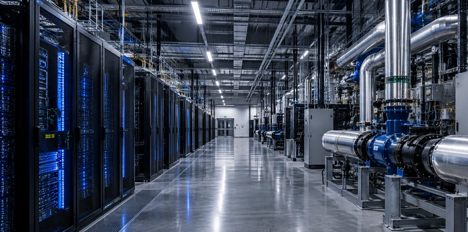
Data Centre Cooling System Types
Data centre cooling system types are easiest to compare by where they capture heat: through room or rack air, at the rack exhaust with a rear-door heat exchanger, at selected components with cold plates, or around immersed IT equipment.
Those heat-capture choices do not describe the whole cooling system. Liquid interfaces, facility plant, heat rejection, retrofit constraints and serviceability still determine whether an architecture fits a particular site. Start with the capture method, then check the downstream dependencies.
- Compare cooling families by the point where they capture IT heat. Chillers, cooling towers, dry coolers and heat-reuse systems sit farther downstream and should not be treated as peer heat-capture types.
- Direct liquid cooling does not automatically remove the need for air cooling. Some components and supporting infrastructure can still reject heat to air, so any remaining air path must be planned explicitly.
- Rack density matters, but it is not a universal technology threshold. Equipment compatibility, retrofit state, climate and water strategy, facility interfaces, resilience and serviceability can all change the shortlist.
Types of data centre cooling systems
Four heat-capture families are the useful starting point for system comparison: air cooling, rear-door heat exchange, cold-plate direct liquid cooling and immersion cooling. Hybrid air-and-liquid operation is better understood as a deployment pattern that combines more than one heat path, not as a fifth universal capture family.
This distinction matters because many technology lists mix the point where IT heat is captured with the equipment that later transports or rejects that heat. A chilled-water plant, a coolant distribution unit or an outdoor heat-rejection system can be essential to an architecture without being the heat-capture method itself.
Air cooling
- Heat capture
- Through controlled supply and return airflow across air-cooled IT equipment.
- Still resolve
- Air delivery and return paths, bypass and recirculation, facility cooling capacity and final heat rejection.
Shortlist questionCan the air path and facility system support the present and planned IT load without creating unacceptable mixing or recirculation?
Rear-door heat exchange
- Heat capture
- At the rack exhaust, where server air passes through an air-to-liquid heat exchanger.
- Still resolve
- Rack airflow, the liquid connection, residual room load, maintenance access and downstream facility cooling.
Shortlist questionDoes rack-level exhaust capture solve the constraint while keeping the existing server-airflow model workable?
Cold-plate direct liquid cooling
- Heat capture
- At selected high-heat components through liquid-cooled cold plates.
- Still resolve
- Which components remain air cooled, the technology-side and facility-side liquid boundaries, fluid condition, serviceability and heat rejection.
Shortlist questionWhich components are actually liquid cooled, and can the IT and facility sides support the required interfaces and maintenance model?
Immersion cooling
- Heat capture
- Around immersed IT equipment in dielectric fluid.
- Still resolve
- Single-phase or two-phase architecture, equipment compatibility, servicing model, downstream heat transport and facility connection.
Shortlist questionCan the IT estate, service model and facility be designed around the chosen immersion architecture?
Where each cooling system acts in the heat path
The technology name tells you only part of the architecture. After heat is captured, it may move through equipment-side, technology-side and facility-side loops before reaching facility cooling plant and the final heat-rejection system. Those layers should be compared separately.
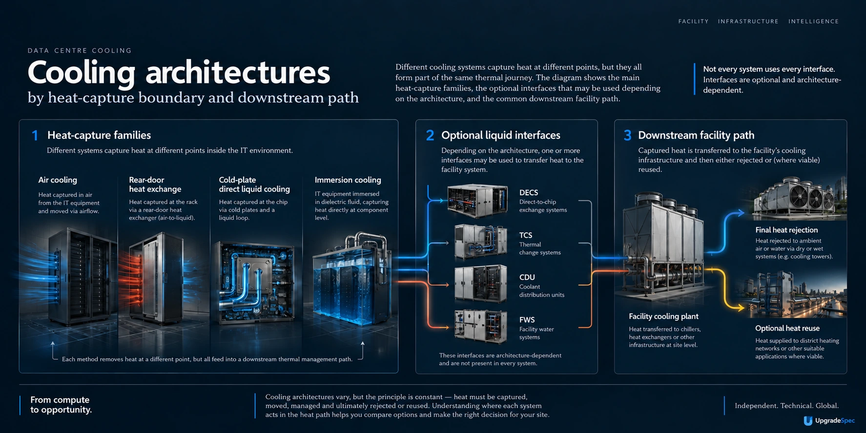
This page uses the layer map only to keep system comparisons clean. The separate how-data-centre-cooling-works guide owns the full thermal-path explanation.
Why liquid cooling does not always remove the air-cooling requirement
Cold plates remove heat from the components they serve, not automatically from every heat-producing part of the rack or room. Other components, power equipment and mixed equipment populations can continue to reject heat to air. That means a liquid-cooling project can still depend on room airflow and facility air-cooling capacity.
The consequence is most important in retrofits. A project may add liquid cooling in stages while existing air-cooled equipment remains in service, so the old and new heat paths have to coexist during migration, commissioning and normal operation.
How to narrow the cooling-system shortlist
There is no single cooling design that is most suitable for every data centre. The useful question is not which technology wins in general, but which architectures remain credible after the project constraints are applied.
Workload and heat density
EstablishCurrent and planned IT load, rack distribution and how the workload is expected to change.
Effect on shortlistHigher density can justify closer investigation of liquid options, but density alone should not force the decision.
IT equipment compatibility
EstablishWhich servers, racks and components support the proposed air, rear-door, cold-plate or immersion approach.
Effect on shortlistDo not assume that a cooling concept is compatible with the installed or planned IT estate without equipment-level confirmation.
Existing facility and retrofit state
EstablishAvailable air and liquid infrastructure, plant capacity, space, phasing constraints and what must remain operational during change.
Effect on shortlistRetrofit friction can make an otherwise credible new-build architecture difficult, staged or operationally risky to introduce.
Climate, water and heat rejection
EstablishSite conditions, water strategy, existing plant and the dependable route for rejecting heat at design conditions.
Effect on shortlistThe downstream facility path can remove options that look attractive when only the rack or chip boundary is considered.
Resilience and operating model
EstablishRequired continuity, maintenance windows, operator skills, commissioning approach and ownership of interfaces.
Effect on shortlistAn architecture that cannot be maintained or commissioned within the operating model is not a complete fit.
Liquid interfaces and serviceability
EstablishFluid quality, filtration, pressure integrity, maintainability and responsibility between IT and facility teams.
Effect on shortlistThese requirements can determine whether a CDU-separated or non-CDU arrangement is practical and who must own the controls.
A practical comparison order
Move from architecture fit to products and suppliers, not the other way around.
- Start with the heat-capture family that fits the IT equipment and workload.
- Identify what heat remains on air and what existing infrastructure must stay.
- Map any liquid interfaces between equipment, technology cooling and facility water.
- Check site conditions, plant and the final heat-rejection path.
- Test retrofit, resilience, commissioning and serviceability constraints.
- Only then compare products, suppliers or detailed performance claims within the surviving architecture paths.
Liquid-cooling interfaces and serviceability
Liquid cooling adds an interface question that is easy to miss in high-level comparisons: where does responsibility move from the IT equipment to the technology cooling system and then to the facility water system? DECS, TCS and FWS are useful terms for keeping those boundaries explicit.
| Boundary or function | Question to resolve | Why it matters |
|---|---|---|
| DECS - data-equipment cooling system | What equipment-side circuit, cold plates or other IT-facing components are included? | It defines the equipment-side responsibility and the fluid conditions that the IT hardware expects. |
| TCS - technology cooling system | Is there a separate technology-side loop, and which functions condition, circulate or protect that loop? | It determines where heat transfer, fluid-quality control and operational responsibility sit between IT and facility systems. |
| CDU separation | Is a CDU used to transfer heat between the technology side and facility water, or are compatible systems connected without a separate CDU? | A separate CDU can provide hydraulic or fluid-quality separation; without it, equivalent functions or responsibilities still need to be addressed elsewhere. |
| FWS - facility water system | What facility-side supply, return and heat-rejection conditions are available? | The IT-cooling architecture still has to hand heat to a facility system that can accept and reject it. |
| Serviceability | Who owns filtration, fluid quality, pressure integrity, isolation, maintenance and recovery at each interface? | A technically workable heat path can still be a poor operational fit if responsibilities or maintenance access are unclear. |
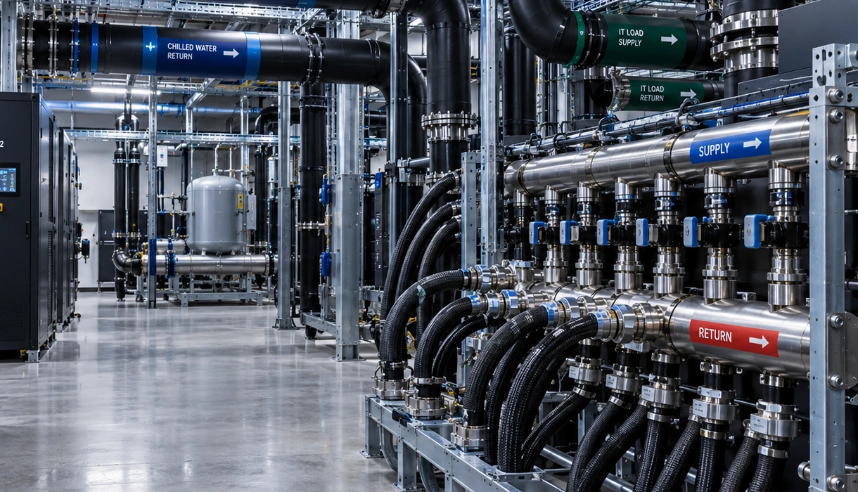
Heat rejection and heat reuse are separate architecture decisions
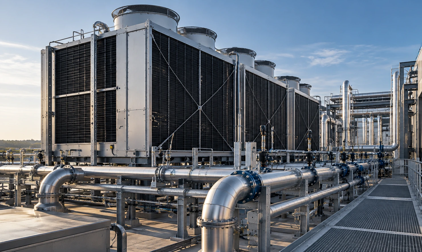
Capturing heat at the rack or component is only the first part of the cooling problem. The site still needs a facility path that can transport and reject that heat under the required operating conditions. Climate, water strategy, existing plant and the final heat sink can therefore change which capture architecture is practical.
Heat reuse is another downstream decision. It can be valuable when there is a receiving demand, but the receiving system will not necessarily accept the data-centre heat at every moment. A dependable fallback heat-rejection path is still required.
Does higher rack density automatically mean liquid cooling?
This page deliberately avoids universal kW-per-rack bands. Use the actual equipment, workload and facility constraints to decide when air, rear-door, cold-plate, immersion or a hybrid arrangement deserves detailed design work.
Terms, standards and the next comparison to make
Standards status matters ISO/IEC AWI TS 22237-44 is an approved work item for liquid-cooling guidance and remains under development. Do not treat it as a published standard; its status should be rechecked before release.
| Term | Use it for | Do not confuse it with |
|---|---|---|
| Heat-capture family | The first method used to remove heat from the IT equipment or its exhaust air. | The downstream plant or outdoor heat-rejection equipment. |
| DECS | The data-equipment cooling system on the equipment side of a liquid architecture. | The complete facility cooling system. |
| TCS | The technology cooling system between equipment-side and facility-side boundaries where that layer exists. | A universal loop that every liquid architecture must contain. |
| FWS | The facility water system that receives heat from the technology or equipment side where applicable. | The IT heat-capture method itself. |
| CDU | A coolant distribution unit used in many liquid architectures to transfer heat and provide separation or conditioning functions. | A mandatory component in every direct-liquid design. |
Reference list14 sources
- Open Compute ProjectCooling EnvironmentsIndustry Association · Global
- ISOISO/IEC AWI TS 22237-44Standards Body · Global
- US Department of EnergyBest Practices Guide for Energy-Efficient Data Center DesignGovernment · United States
- ASHRAEWater-Cooled Servers: Common Designs, Components, and ProcessesStandards Body
- Open Compute ProjectDoor Heat Exchanger RequirementsIndustry Association
- Open Compute ProjectImmersion Requirements Rev. 2.10Industry Association
- Open Compute ProjectACS Liquid Cooling Cold Plate RequirementsIndustry Association
- Open Compute ProjectLiquid to Liquid CDU Test MethodologyIndustry Association
- ASHRAEEnergy and Thermal Efficiency - AI Data Center Energy Performance FrameworkStandards Body · Global
- ASHRAE, PNNL and NEMAAI Data Center Energy Performance Framework - Introduction and PurposeStandards Body · Global
- ASHRAE, PNNL and NEMAAI Data Center Energy Performance Framework - Retrofit and Modernization StrategiesStandards Body · Global
- Uptime Institute2026 Cooling Systems Survey [Results and Crosstab files]Industry Research · Global
- Uptime InstituteLower density brings server efficiency and cooling gainsIndustry Research · Global
- International Telecommunication UnionITU-T L.1327 (08/2024) - Guidelines on the selection of cooling technologies for data centres in multiple scenariosStandards Body · Global
Limitations
- No single cooling design is universally most suitable or most efficient.
- No universal rack-density threshold determines when liquid cooling must be used.
- No supplier ranking, product compatibility or product recommendation is made here.
- No global price range is used to choose between architectures.
- Jurisdiction-specific requirements are not generalised into a global rule.
- Detailed thermal-path mechanics belong in the dedicated how-data-centre-cooling-works guide.